DEEP SEWER REPAIR | STERLING HEIGHTS, MI
Drilled shafts inside a shaft: Constructing secant piles under low overhead power lines
On Christmas Eve of 2016, a section of the Macomb County Interceptor Sewer collapsed, which led to a massive sinkhole at the ground surface. This dramatic event caused an evacuation of nearby residents as well as an emergency repair. After the localized repair was performed, design work started on re-lining approximately 7,000 feet of the sewer to avoid future problems with the aging tunnel, which was originally constructed in 1973.
GENERAL CONTRACTOR

DESIGN/BUILD SPECIALITY CONTRACTOR


BACKGROUND
Located in Sterling Heights, Michigan, the sewer tunnel was 11 feet in diameter and approximately 50 feet below grade along a stretch of 15-Mile Road.
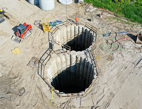
The original sewer was constructed with unreinforced concrete, up to 18 inches in thickness. As part of the re-lining project, it was decided to locate construction activities in a utility corridor to minimize disruption to traffic. The utility corridor contained multiple overhead high-voltage power lines and was located off to the side of 15-Mile Road. Ground conditions dictated the use of a cutoff wall; however, the overhead power lines restricted the equipment which could be used. The resulting design consisted of an access shaft with two different wall types.
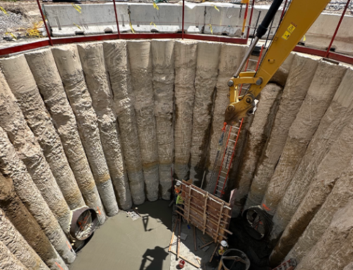
The upper 42 feet was composed of ring beams and wood lagging, while the lower section included reinforced concrete secant piles. Conceptually, a large rotary drill rig could fit within the upper shaft in order to construct the lower circular secant pile shaft.
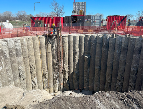
Schnabel Geostructural Design & Construction was hired by Oscar Renda to install the 34.5 foot inside diameter secant pile shaft. This work consisted of 60 overlapping secant piles ranging from eight feet to 51 feet in depth. Shallow drill depths of 8 to fourteen feet followed the top radius of the tunnel. Once clear of the tunnel to the sides, 38 feet deep primary shafts and 51 feet deep secondary shafts were drilled below subgrade to ensure basal stability of the excavation. Reinforcing steel consisting of W21x182 wide flange sections were placed in secondary shafts.
ASSEMBLY & JOB PREP
Months of planning from an equipment and safety standpoint went into this project. The unique construction technique of low-overhead secant piles had many obstacles to plan around. First was lowering a 200,000 pound drill rig in sections into the upper shaft. Second was assembling the rig with a 70 foot tall mast inside of a 45 foot wide shaft. Third was constructing the secant piles with limited access for people, support equipment and material installation.

Elevation view of secant piles around sewer

Lowering base of rig into shaft
DRILLING & CONSTRUCTION
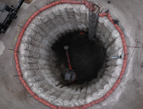
Once assembled, the drilling was similar to other jobs with the main difference being that it took place inside of a 45-foot diameter cell at a depth of 42’ below ground surface.
Careful planning was implemented to overcome the operational challenges. Drill tooling was kept to a minimum to allow as much room as possible within the shaft. A self-dumping box to spin spoils into and then lift out of the upper shaft with a service crane was utilized. There was inherently some drill spoil which did not get into the spoil box by mechanical means. This was addressed with ground workers who had to shovel any extra spoil by hand. Due to safety concerns, only two people were allowed on the ground inside the shaft at a time.
No other normal support equipment, such as a skid steer, loader, forklift or manlift were allowed inside the shaft as there physically was not enough room.
Three main soil layers were encountered while drilling. The upper 25 feet consisted of a silty clay, which was dry and stayed on the auger flights. Some of the shallow secant piles above the sewer stayed in this layer and were drilled relatively easily. From 25 to 45 feet, sand below the water table was encountered. To effectively excavate this material, the drill hole was kept flooded during drilling.


CONCLUSION
Once assembled, the drilling was similar to other jobs with the main difference being that it took place inside of a 45-foot diameter cell at a depth of 42’ below ground surface.
Careful planning was implemented to overcome the operational challenges. Drill tooling was kept to a minimum to allow as much room as possible within the shaft.
A self-dumping box to spin spoils into and then lift out of the upper shaft with a service crane was utilized. There was inherently some drill spoil which did not get into the spoil box by mechanical means.
This was addressed with ground workers who had to shovel any extra spoil by hand. Due to safety concerns, only two people were allowed on the ground inside the shaft at a time.
No other normal support equipment, such as a skid steer, loader, forklift or manlift were allowed inside the shaft as there physically was not enough room.
Three main soil layers were encountered while drilling. The upper 25 feet consisted of a silty clay, which was dry and stayed on the auger flights. Some of the shallow secant piles above the sewer stayed in this layer and were drilled relatively easily. From 25 to 45 feet, sand below the water table was encountered. To effectively excavate this material, the drill hole was kept flooded during drilling.