Waldo’s Old Fourth Ward Project | Georgia
City: Atlanta
State: Georgia
General Contractor: Shell McElroy
Waldo’s Old Fourth Ward (O4W) Project Information
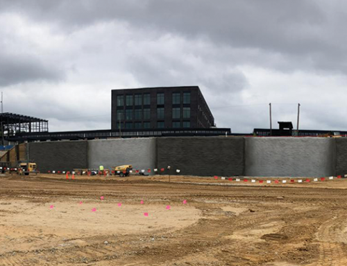
Schnabel was hired to design and install a temporary soil mixed cut-off wall system for the Waldo’s project in Atlanta, GA. Named after Ralph Waldo Emerson, The Waldo’s project is a mixed-use development located in the eclectic Old Fourth Ward (O4W) neighborhood. When complete, the project will be anchored by a mass timber office building, 147-room hotel, townhomes, and retail. The project includes 275 below-street level parking spaces.
Cut-Off Wall Construction on the Waldo’s O4W Project
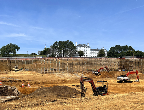
The project makes up most of the city block, except for the north side, which is partially bordered by a parking lot and single-family homes. One single-family home was approximately 5 feet from the face of the proposed shoring. Historically, this type of project would be constructed with a conventional soldier beam and lagging system combined with underpinning of the nearest structures. In this case, temporary and permanent dewatering to construct and use the below-ground parking structure was required. Dewatering systems for excavation can lower the water table outside the project and lead to settlement of the adjacent structures. A cut off wall allowed the excavation to be dewatered without lowering the water table outside the excavation. A cut-off wall is typically stiffer than conventional soldier beams and lagging, so therefore, potential deflections outside the project were greatly limited without having to obtain permission to underpin the adjacent existing structures.
Site Conditions on the Waldo’s O4W Project
The project is in the Piedmont Geologic Region with soil conditions consisting of 3 to 13 feet of manmade fill over residual soil. Below the residual soil, partially weathered rock (PWR), a transitional zone between soil and rock defined locally by standard penetration resistances exceeding 100 blows per foot, was encountered between 43 and 78 feet below the ground surface. Auger refusal material, which cannot be penetrated by the soil test boring drilling equipment, was located between 47 and 80 feet below the ground surface. Groundwater readings varied from 7 to 12 feet below the ground surface and are known to fluctuate 5 to 10 feet seasonally.
Soil-Mixed Wall Construction on the Waldo’s O4W Project
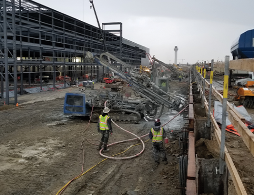
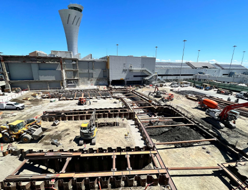
The soil-mixed wall was approximately 1,100 feet long around the entire perimeter of the site with an exposed height between 20 and 32 feet. The mixing tools were configured to create three 36-inch diameter shafts. The grout mixing and delivery system used a vertical silo, high-volume batch plant, and grout pumps. Drilling spoils were managed with an excavator and soldier beams were installed with a crawler crane and vibratory hammer as needed.
Lateral Support for the Waldo’s O4W Project
Lateral support was provided by 1 to 3 tiers of tiebacks. Tiebacks above the water table were installed with open-hole drilling and air flushing. Below the adjacent home and the water table, temporary casing and water flushing were used to maintain hole stability and limit ground and water loss. A Klemm anchor drill rig, cement silo, grout plant, and testing equipment were used to complete the tieback work.
Survey Data Collect During the Waldo’s O4W Project
A significant amount of survey data was collected during the project to monitor performance. Automated total stations, piezometers, and vibration sensors collected data every few hours throughout the project and posted that data to a web portal for the entire project team to monitor. Survey data was collected with prisms mounted at the top of the soldier beams and nearby structures to monitor lateral and vertical deflections. The piezometers were installed to monitor the groundwater table and connected to recharge pumps. When the water table outside the project lowered more than 2.5 feet below the baseline elevation, the recharge pumps would run until the water level returned to the acceptable range. The lateral deflections of the shoring system and the settlement of structures outside the project were below the required limits. The project proved that a soil mix cut-off wall could be successfully constructed in the Piedmont soils and limit deflections of nearby structures during dewatering without underpinning.